fn milling mashine control circuit diagram
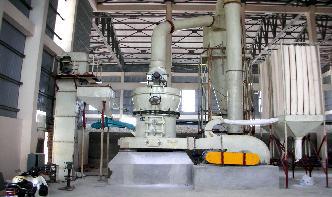
Closed Circuit Grinding VS Open Circuit Grinding
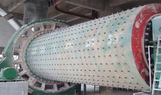
Metallurgical ContentOpen Circuit GrindingClosed Circuit GrindingGrinding Circuit Process Control VariablesGrinding Operating Costs The simplest grinding circuit consists of a ball or rod mill in closed circuit with a classifier; the flow sheet is shown in Fig. 25 and the actual layout in Fig. 9....
Converting a 440V lathe to 220V | The HobbyMachinist
Aug 26, 2013· Converting a 440V lathe to 220V. Thread starter rhowell; Start date Aug 18, 2013 [3] ... First, the machine will draw twice the current, so the heaters (overcurrent protection) in the contactors (relays) used to control the motor(s) will need to be changed. ... If it does theres typically a wiring diagram either on the plate or under the wiring ......
Simple Diagram Of Milling Machine 9261
Schematic Diagram Of Vertical Milling MachineOperation Performed On Milling machine With Diagrams. It is the operation of production of a flat vertical surface on the ... Performed On Milling machine With Diagrams by ... and diagram of milling machine....
Introduction to cnc machines (1) SlideShare
Introduction to cnc machines (1) ... • Float switches Schematic diagram of a CNC machine tool A CNC system consists of the following 6 major elements: a. ... Programmable controllerThe statement list describes the automation task by means of mnemonic function control system flowchart is a graphic representation ......
STEPPER MOTOR CONTROL USING LABVIEW IN A .
1. To replace the existing servo motors with stepper motors control system for the desktop CNC milling machine. 2. To develop a driver and an interface circuit between the CNC machine and a PC. 3. To develop a LabVIEW program that can generate machine ....
Pneumatic Circuit Symbols Explained |
Pneumatic Circuit Symbols Explained. Directional air control valves are the building blocks of pneumatic control. Pneumatic circuit symbols representing these valves provide detailed information about the valve they represent. Symbols show the methods of actuation, the number of positions, the flow paths and the number of ports....
VFD simple explanation YouTube
Oct 07, 2016· vfd function, vfd for lathe, ... vfd milling machine, vfd mach3, vfd motor control abb, morningside vfd, mvfd 27, ... vfd wiring, vfd watch, vfd wiring diagram, how do vfd work,...
Help Me/ hook up a forwardstopreverse motor cont switch ...
Aug 11, 2012· I have a bad switch on my machine and was given this new switch by a dealer of these milling machines, but its very different looking in the way its hooked up than the one on my machine ... Other mill wiring motor diagram from above PDF Switch schemtaic from other mills PDF . Last edited: Aug 6, 2012. Aug 7, 2012 #15. sea. 28 0....
wiring circuit of grinding machine
wiring circuit of grinding machine small ball mill, Wiring Diagrams LittleMachineShop wiring circuit of grinding machine cement grinding circuit modification close circuit grinding mills hydraulic circuit . ... ballmill instumintion control circuit diagram, and wiring diagrams, Ball mill is the main bauxite grinding machine used in ......
How to Read a Schematic
How to Read a Schematic; ... Each pin should be labeled with both a number, and a function. Schematic symbols for an ATmega328 microcontroller (commonly found on Arduinos), an ATSHA204 encryption IC, and an ATtiny45 MCU. As you can see, these components greatly vary ....
Hmt Machine Tools Milling Machine Fn3 Wiring Diagram
fn3 milling mashine control circuit diagram. hmt fn 3 milling machine sales . hmt machine tools milling machine fn3 wiring diagram. hmt machine tools milling machine fn3 wiring diagram hmt hmt fn two vertical milling price ...
Cnc Circuit Diagram
Cnc Circuit Diagram Stepper motor controller driver circuit with circuit design, Description. here is the circuit ... power feed circuit diagram vertical milling machine operation labeled diagram of cnc milling machine 80 ... CNC SYSTEMS 1213 INTRODUCTION 12 CONTROL SYSTEM 13, 6. Schematic diagram of a CNC machine tool A CNC ......
Failsafe Design | Ladder Logic | Electronics Textbook
The goal of failsafe design is to make a control system as tolerant as possible to likely wiring or component failures. The most common type of wiring and component failure is an "open" circuit, or broken connection. Therefore, a failsafe system should be designed to default to its safest mode of operation in the case of an open circuit....
CX612 Manual Busy Bee Tools
familiar with your machine's control panel before operation. Figure5 Control panel A. ON SPEED CONTROL KNOB: The CX612 is a variable speed milling machine and features a speed control knob. This buttons turns the milling machine ON and controls the spindle RPM. B. POWER INDICATOR LIGHT. This light shines when power is ON....
Wiring Diagrams
Wiring Diagrams. These wiring diagrams show different applications of the controller boards we sell. Diagram Number ... Wiring diagram for late model mini mill with red and yellow emergency stop switch. ... LMS 1211: 3156: Wiring diagram for late model harbor freight mini lathe with illuminated rocker power switch and safety interlock circuit ......
All Fadal Manuals Complete documention in PDF format
Fadal Manuals: Below is a complete source for all the documentation that was originally shipped with your Fadal machines. ... Twenty Two wiring diagrams of the machine; the Fadal CNC wiring, the Spindle Drive plus all motors, I/O, fuses and relays. Axis Drive System: All about AC and DC Amplifiers, SV command, Axis Motors, Lube, Cool Screws ......


